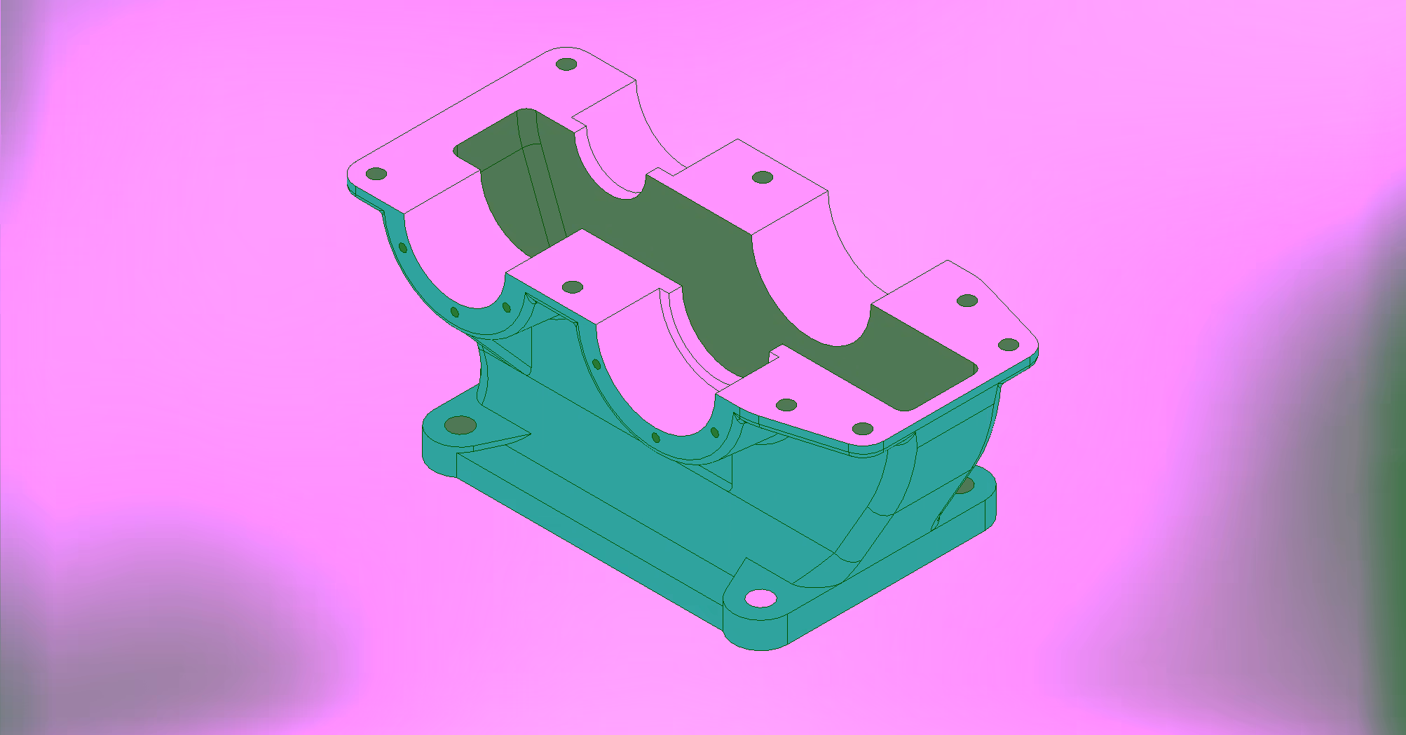
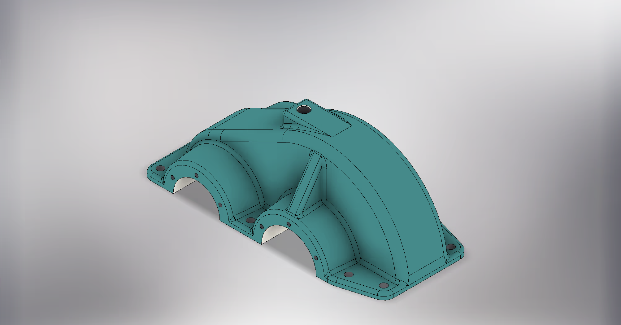
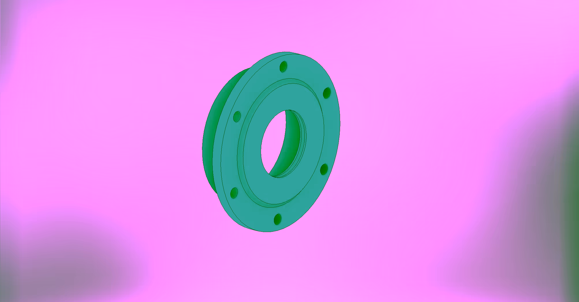
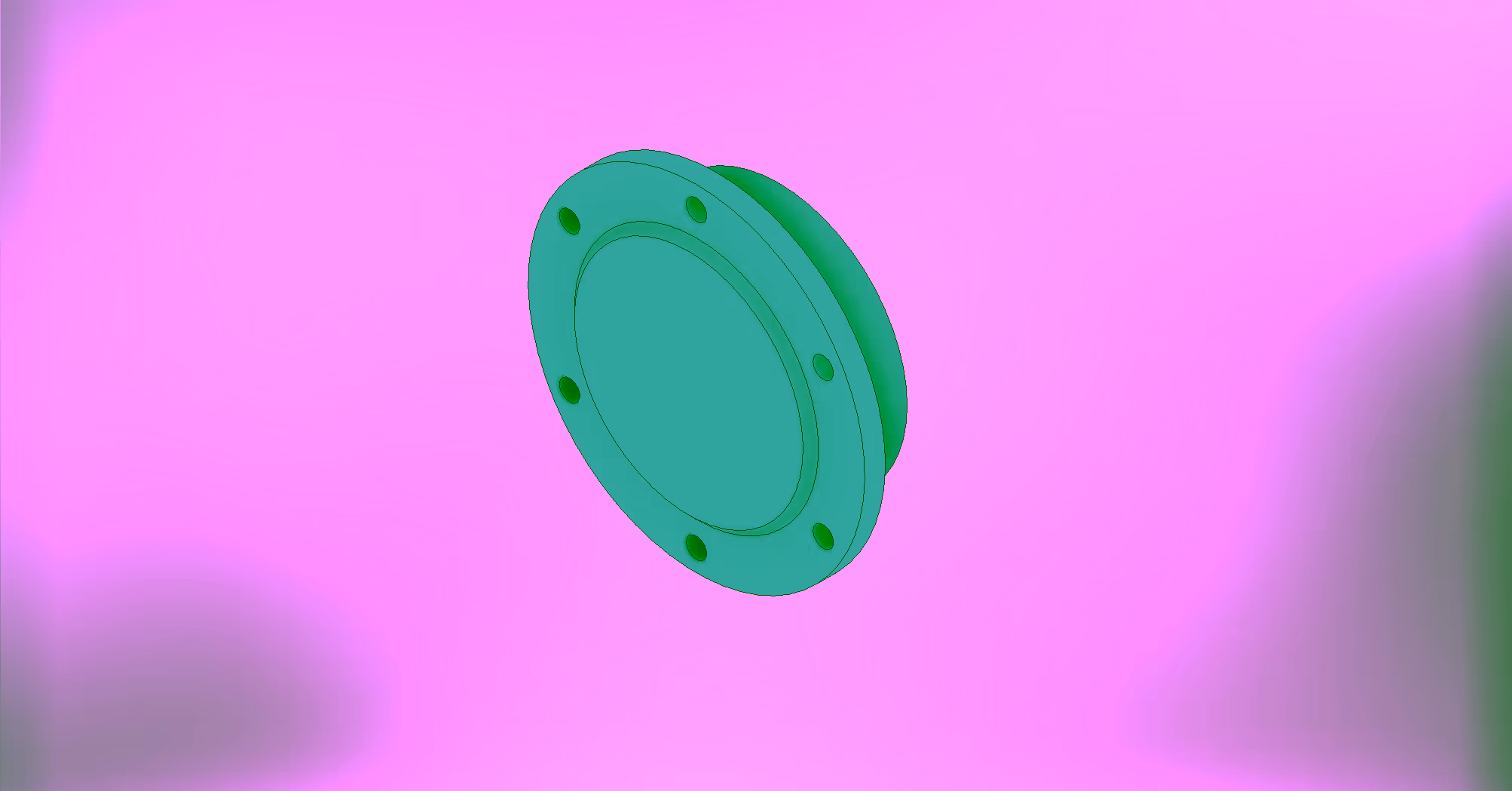
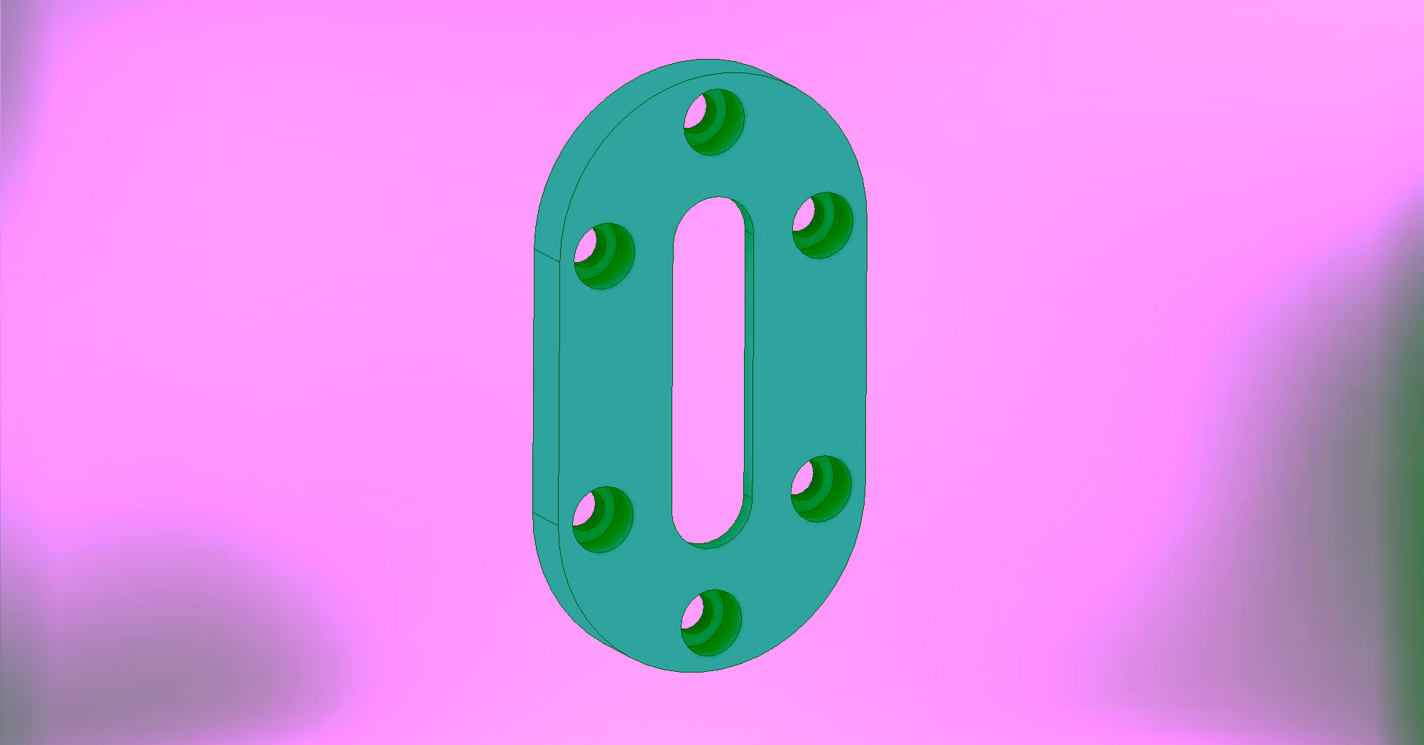
The Project
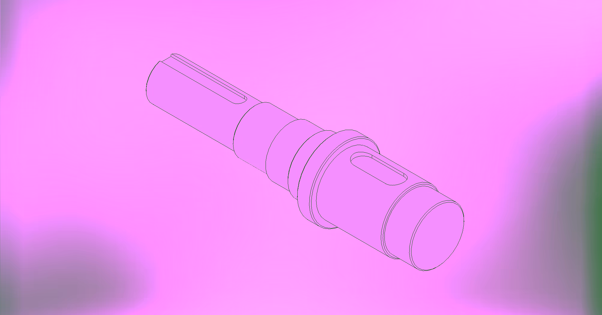
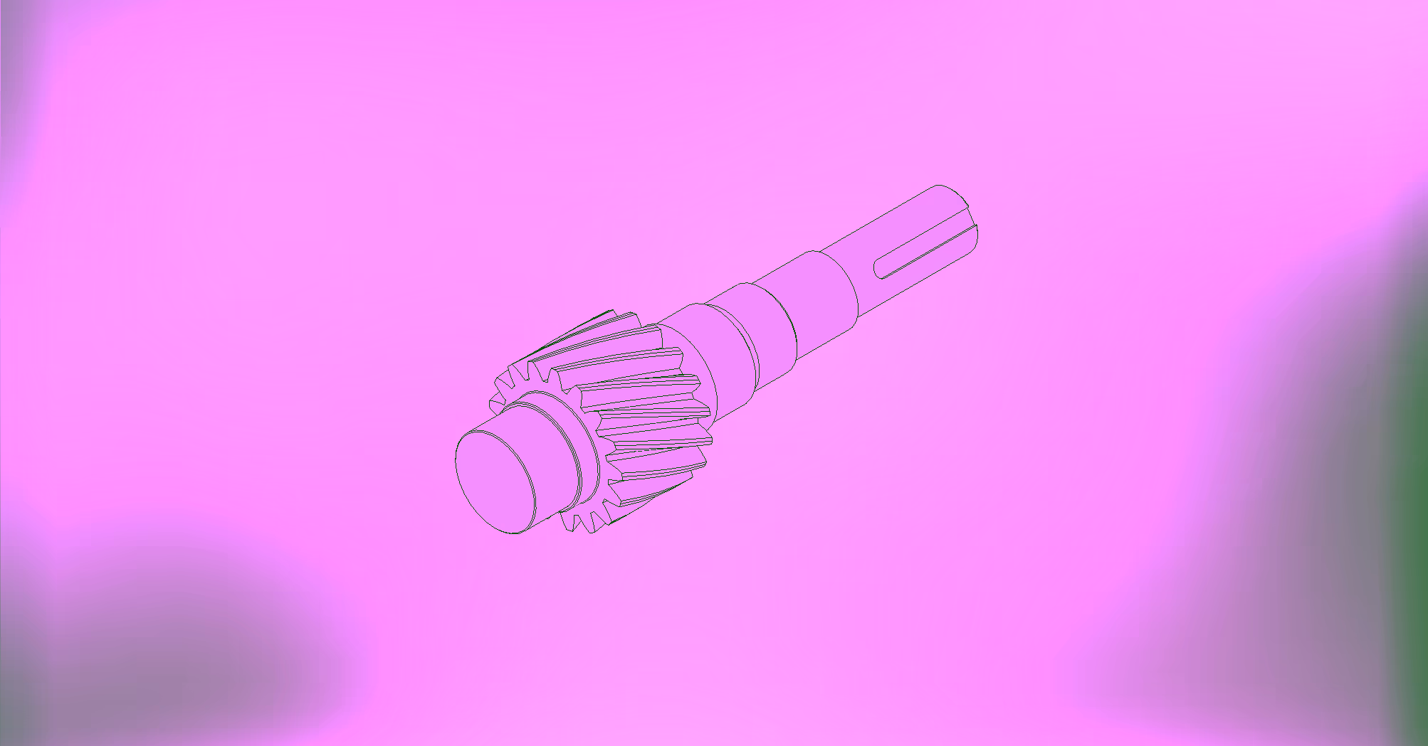
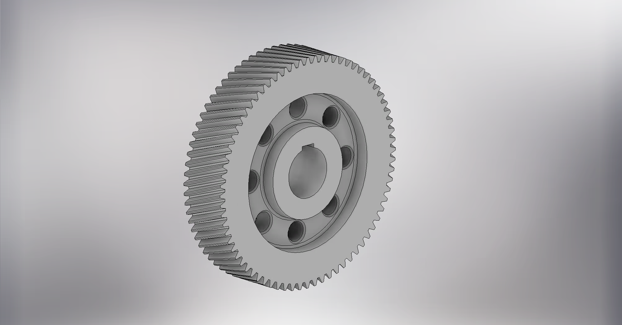
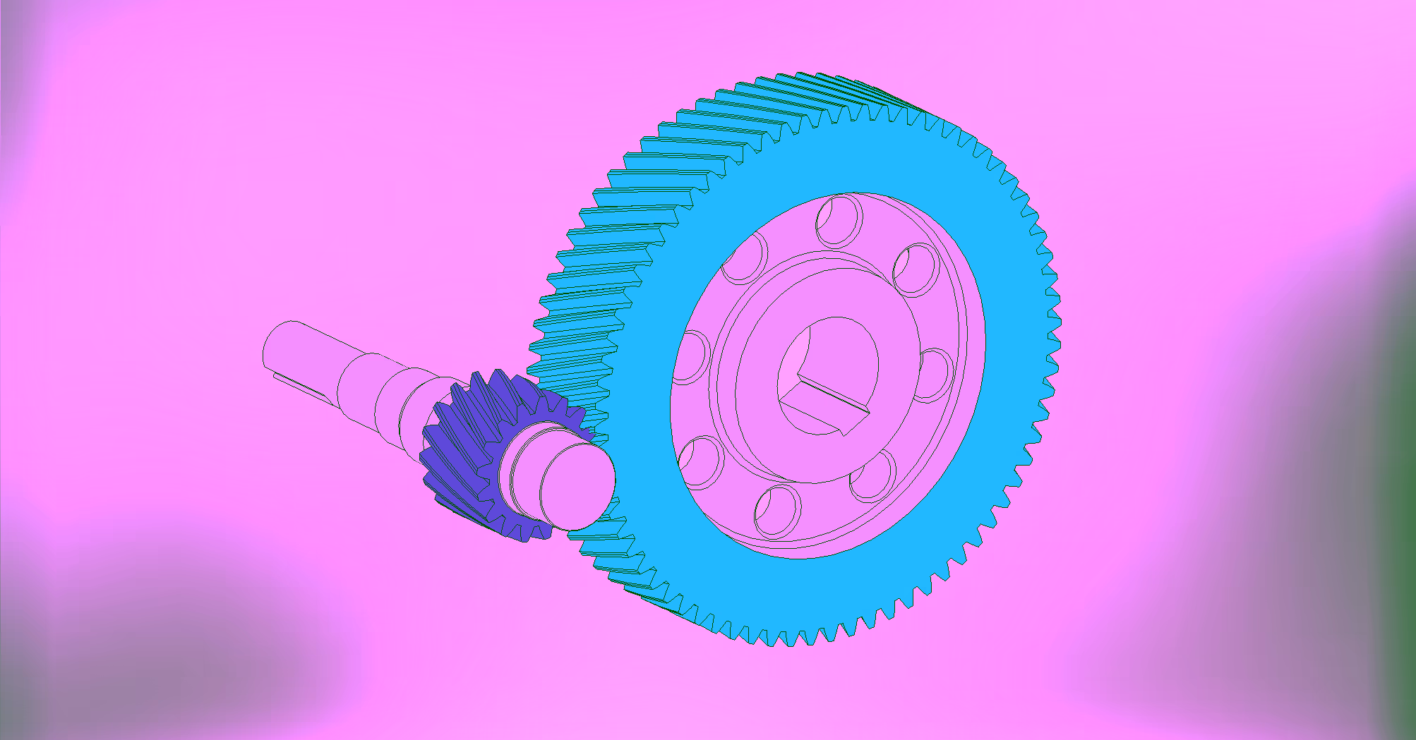
The choice of helical gear topology for the first stage of this speed reducer is based on the need to combine kinematic precision, high load transmission capacity, and operation with low noise and vibration levels. The pinion-gear pair was designed to reduce the input speed from 1000 RPM to approximately 233 RPM, delivering an effective transmission ratio of i = 4.2941, with an insignificant deviation from the nominal target of 4.3.
The adoption of a helix angle β of 20º and a pressure angle α of 20º ensures a high contact ratio (total contact ratio ε ≈ 2.73). This means that the load is distributed gradually and supported by multiple teeth simultaneously, mitigating mechanical shocks in the meshing (single overload factor KAS = 1.0) and optimizing the system's service life under continuous operation.
From a metallurgical and structural perspective, the selection of 18CrNiMo7-6 (~SAE 4320) alloy steel offers an excellent combination of core toughness (yield strength Sy = 800 MPa) and high surface hardness on the flanks after heat treatment (380 HV). The strength calculations, based on the ISO 6336:1996 standard, attest to the extreme robustness of the design for the 1 kW power rating: the safety factor against contact fatigue (pitting) resulted in SH ≈ 3.44, while the safety factor against tooth root breakage (bending) exceeds the mark of SF > 17. These values ensure not only technical viability but superior operational reliability against catastrophic failures.
Technical Details
Calculation Memorial
Helical Gear Drive Component Generator
Project output · Total profile shift · Profile shift distribution per Merrit · Torque calculation for specified power and rotational speed
Calculation confirms design compatibility.
General Pair Parameters
Gear Geometry
| Parameter | Symbol | Gear 1 | Gear 2 | Unit |
|---|---|---|---|---|
| Number of teeth | z | 17 | 73 | — |
| Profile shift coefficient | x | 0.3164 | −0.2036 | — |
| Reference (pitch) diameter | d | 63.319 | 271.897 | mm |
| Tip (outside) diameter | da | 71.128 | 276.066 | mm |
| Root diameter | df | 58.674 | 263.612 | mm |
| Base circle diameter | db | 59.044 | 253.543 | mm |
| Working pitch diameter | dw | 63.467 | 272.533 | mm |
| Face width | b | 60.000 | 50.000 | mm |
| Face width coefficient | br | 0.7897 | 0.1839 | — |
| Addendum coefficient | a* | 0.8000 | 0.8000 | — |
| Dedendum clearance coefficient | c* | 0.1800 | 0.1800 | — |
| Root fillet radius coefficient | rf* | 0.2735 | 0.2735 | — |
| Normal tooth thickness | s | 6.304 | 4.979 | mm |
| Transverse tooth thickness | st | 6.709 | 5.299 | mm |
| Chordal tooth thickness | tc | 5.567 | 4.397 | mm |
| Chordal addendum | ac | 2.891 | 1.284 | mm |
| Base tangent length (span) | W | 27.584 | 101.943 | mm |
| Number of teeth spanned | zw | 3.000 | 10.000 | — |
| Measurement over pins (MOP) | M | 72.988 | 278.835 | mm |
| Pin diameter | dM | 6.000 | 6.000 | mm |
| Helix angle tolerance limit | Fβ | 0.0140 | 0.0150 | mm |
| Total radial composite deviation limit | Fr | 0.0210 | 0.0280 | mm |
| Single pitch deviation limit | fpt | 0.0085 | 0.0090 | mm |
| Base pitch deviation limit | fpb | 0.0080 | 0.0085 | mm |
| Equivalent (virtual) number of teeth | zv | 20.175 | 86.634 | — |
| Virtual reference diameter | dn | 70.612 | 303.218 | mm |
| Virtual tip diameter | dan | 78.421 | 307.387 | mm |
| Virtual base circle diameter | dbn | 66.354 | 284.932 | mm |
| Profile shift without tip narrowing | xz | 0.3037 | −1.5182 | — |
| Profile shift without undercut | xp | −0.3800 | −4.2671 | — |
| Profile shift with permissible undercut | xd | −0.5133 | −4.4004 | — |
| Tip relief (addendum shortening) | k | 0.0009 | 0.0009 | — |
| Tip land thickness coefficient | sa | 0.7996 | 0.9800 | — |
| Tip pressure angle | αa | 33.2250 | 22.2558 | deg |
Loads & Forces
| Parameter | Symbol | Gear 1 | Gear 2 | Unit |
|---|---|---|---|---|
| Power | P | 1.000 | 0.980 | kW |
| Rotational speed | n | 1000.00 | 232.88 | rpm |
| Torque | T | 9.549 | 40.186 | N·m |
| Efficiency | η | 0.980 | — | — |
| Radial force (separating) | Fr | 118.630 | — | N |
| Tangential force (transmitted) | Ft | 300.923 | — | N |
| Axial (thrust) force | Fa | −109.527 | — | N |
| Normal (resultant) force | Fn | 341.635 | — | N |
| Pitch line velocity | v | 3.315 | — | m/s |
| Resonance speed | nE | 119,379.991 | — | rpm |
Material — 18CrNiMo7-6 (~SAE 4320)
Additional Load Factors
| Factor | Symbol | Gear 1 | Gear 2 |
|---|---|---|---|
| Application factor | KA | 1.200 | — |
| Dynamic factor | KHv | 1.078 | 1.078 |
| Face load factor | KHβ | 3.281 | 2.541 |
| Transverse load factor | KHα | 2.120 | 2.120 |
| Single overload factor | KAS | 1.000 | — |
Contact Factors
| Factor | Symbol | Gear 1 | Gear 2 |
|---|---|---|---|
| Elasticity factor | ZE | 189.812 | — |
| Zone factor | ZH | 2.351 | — |
| Contact ratio factor | Zε | 0.922 | — |
| Single pair tooth contact factor | ZB | 1.000 | 1.000 |
| Life (durability) factor | ZN | 1.000 | 1.000 |
| Lubricant factor | ZL | 0.967 | — |
| Surface roughness factor | ZR | 1.000 | — |
| Velocity factor | Zv | 0.973 | — |
| Helix angle factor | Zβ | 0.969 | — |
| Size factor | ZX | 1.000 | 1.000 |
| Work hardening factor | ZW | 1.000 | — |
Bending Factors
| Factor | Symbol | Gear 1 | Gear 2 |
|---|---|---|---|
| Tooth form factor | YFa | 1.930 | 1.982 |
| Stress correction factor | YSa | 2.065 | 1.988 |
| Ground root factor | YSag | 1.000 | 1.000 |
| Helix angle factor | Yβ | 0.833 | — |
| Contact ratio factor | Yε | 0.822 | — |
| Alternating bending factor | YA | 1.000 | 1.000 |
| Manufacturing technology factor | YT | 1.000 | 1.000 |
| Life (durability) factor | YN | 1.000 | 1.000 |
| Notch sensitivity factor | Yδ | 1.281 | 1.258 |
| Size factor | YX | 1.000 | 1.000 |
| Root surface condition factor | YR | 1.000 | — |